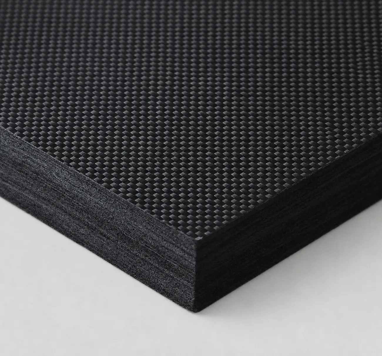
Rigid felt is not a single material but a hot-zone system engineered across four dimensions: precursor selection, process route, geometric form, and purity grade. In 1500–2200°C vacuum or inert atmospheres, it must simultaneously deliver low thermal conductivity (suppressing T4 radiation), dimensional stability, high purity (semiconductor-grade metallic ions < 20 ppm), and erosion resistance under high-velocity argon flow. These are baseline requirements for SiC PVT, 12-inch CZ, and fiber drawing hot zones.
AYD CarboniteX® operates both pitch-based short-fiber wet-laid molding and rayon-based long-fiber solidified winding in parallel. Combined with in-house RefineU pitch precursor, ±0.005 g/cm³ density precision, and semiconductor-grade purification with ash below 20 ppm, the process chain runs from raw pitch to UID-etched delivery for components from SiC PVT chambers to 1.7 m fiber drawing cylinders.
Wet-laid molding + solidified winding, covering both short-fiber density precision and long-fiber thermal-shock toughness.
AYD operates two independent production lines: pitch-based short-fiber wet-laid molding (vacuum slurry pressing) and rayon-based long-fiber solidified winding (soft felt impregnation + heated mandrel winding). The two routes match induction- and resistance-heated furnaces respectively, sharing the same downstream carbonization, graphitization, deep purification, and UID digital traceability.
Pitch-Based Short-Fiber Wet-Laid Molding
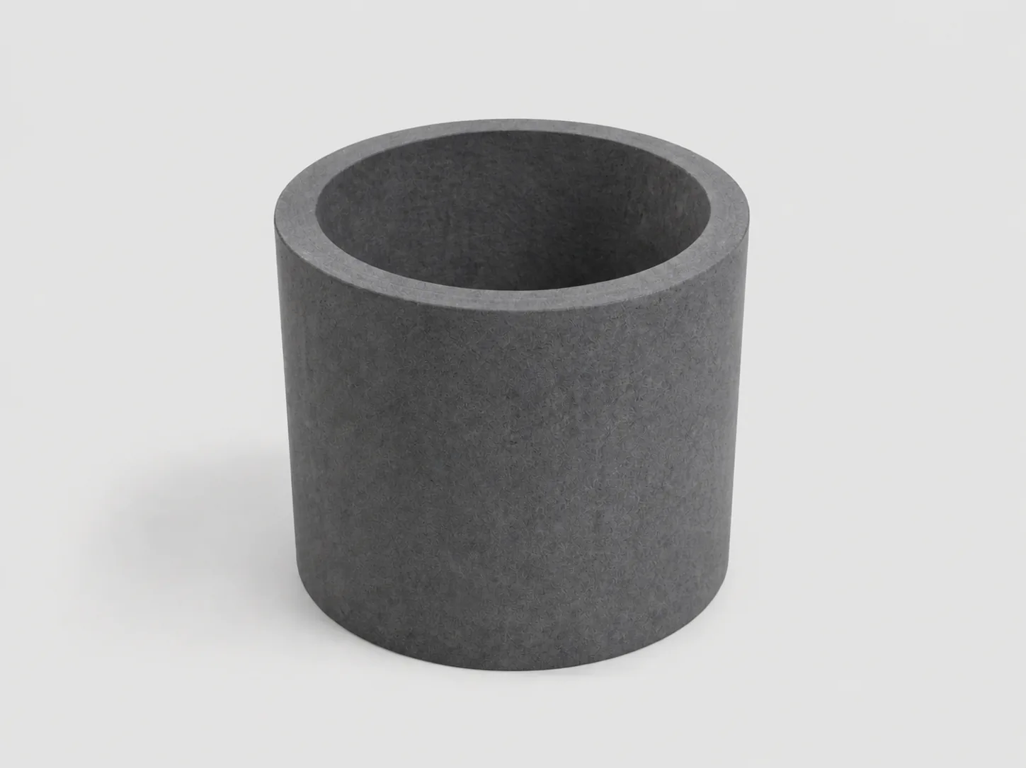
Rayon-Based Long-Fiber Solidified Cylinder Winding
Not just a felt block.
Engineering hot-zone temperature gradients through fiber orientation.
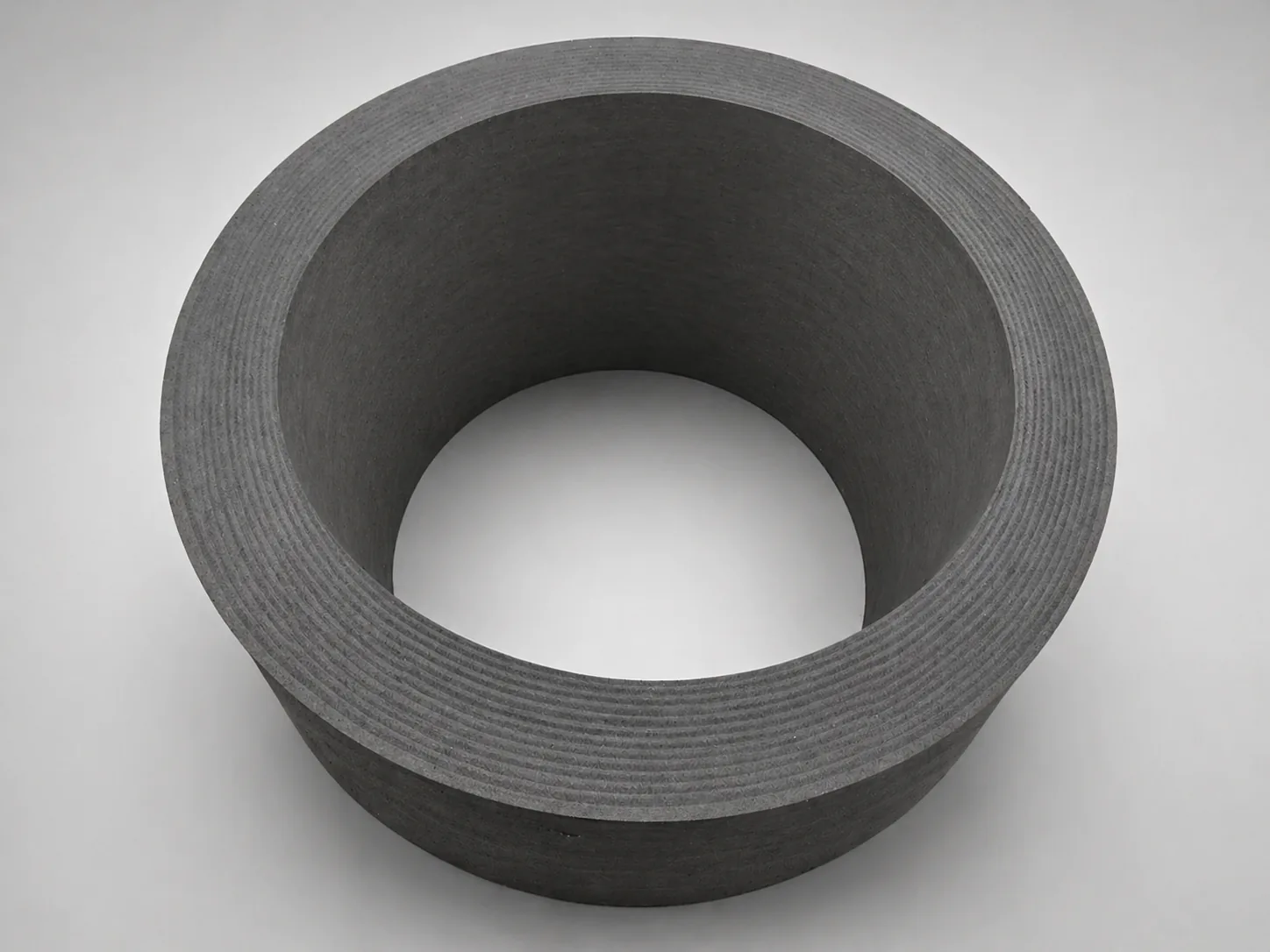
The real engineering value of rigid felt lies in precise fiber-orientation control. In both wet-laid molding and solidified winding routes, AYD aligns fibers to match the customer’s hot-zone requirements: circumferential in cylindrical parts, parallel-stacked in plate parts. Heat propagates preferentially along fiber direction; thermal resistance perpendicular to fibers is significantly higher. Same material, same density, different fiber orientation yields different temperature-gradient direction inside the hot zone.
Cylindrical
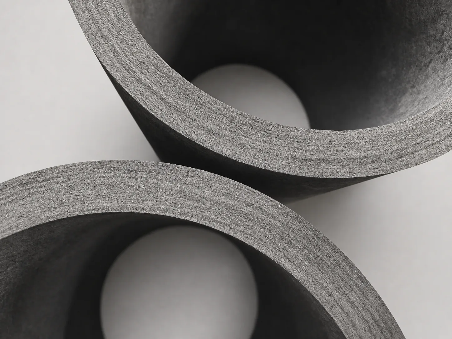
Fibers wound circumferentially. Heat radiating outward from the chamber must cross fiber layers (perpendicular direction), encountering higher thermal resistance. Specified for crystal growth furnace sidewalls and SiC PVT inner crucibles. Designed to suppress radial heat loss and improve furnace efficiency.
Plate
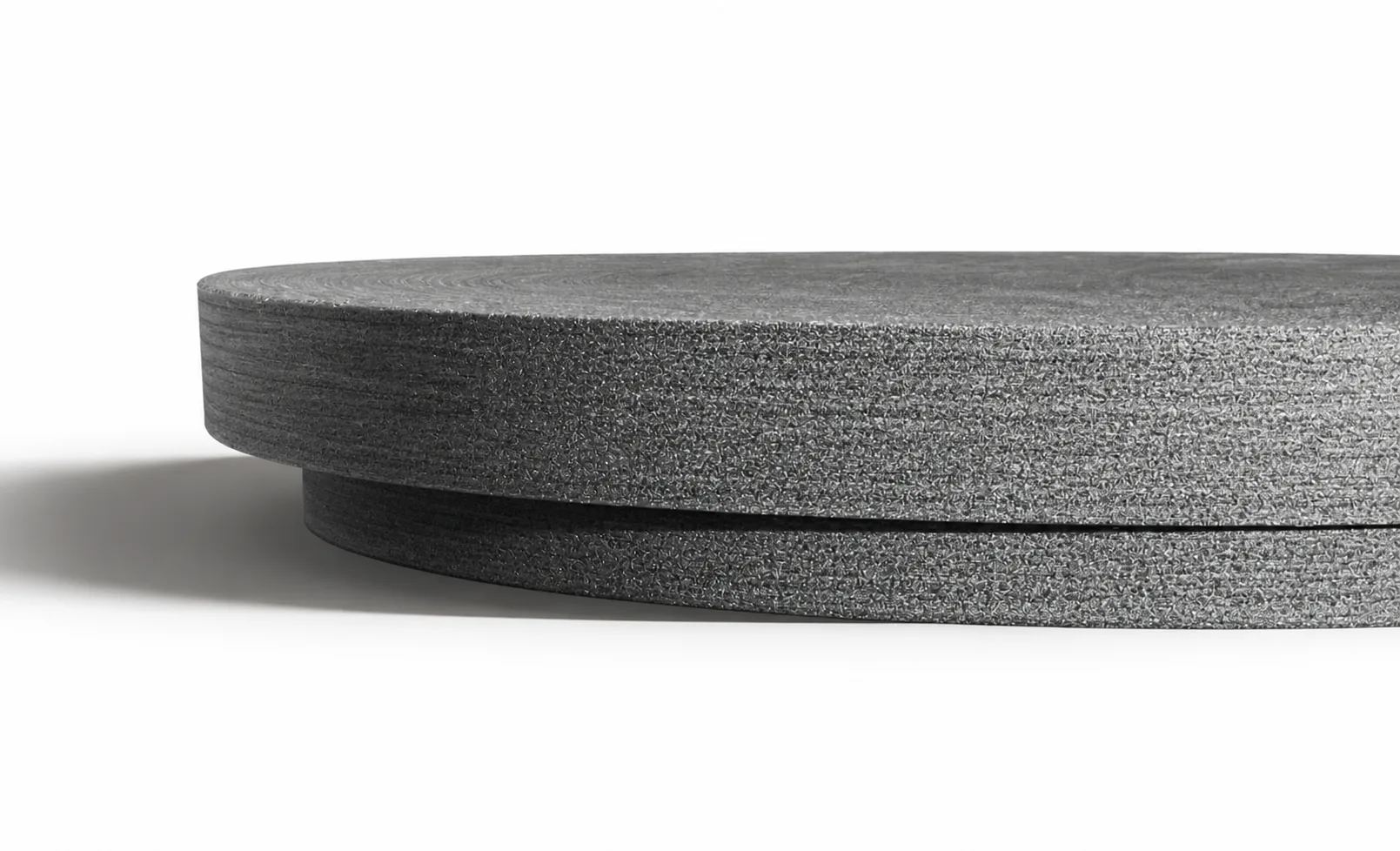
Fibers stacked in parallel layers. Heat traveling top-to-bottom (or reverse) must traverse each layer (perpendicular direction); inter-layer thermal resistance is high. Specified for furnace top covers, bottom plates, and heat-shield discs. Designed to control the shape and steepness of vertical temperature gradients.
Three precursors × three grades, full-spectrum coverage from industrial to semiconductor.
CarboniteX® rigid felt is classified by precursor into pitch-based short-fiber (IPS), rayon-based short-fiber (IRS), and rayon-based long-fiber (IRL). Each precursor offers three purity grades: standard (≤200 ppm), graphitized (≤100 ppm), and semiconductor-grade purified (<20 ppm). All grades share ±0.005 g/cm³ density precision and UID full traceability. Key properties for each precursor are listed below.
IPSPitch-Based Short-Fiber Rigid Felt (Wet-Laid Molding) · 11 properties × 3 grades Expand
| Property | Unit | StandardAYD/S | GraphitizedAYD/S-G | Semi GradeAYD/S-P | Note |
|---|---|---|---|---|---|
| Density | g/cm³ | 0.14–0.25 | Higher density on request | ||
| Carbon Content | wt% | > 99 | > 99.9 | > 99.99 | |
| Ash | ppm | ≤ 200 | ≤ 100 | ≤ 20 | |
| Thermal Cond. (700°C) | W/(m·K) | 0.129 | 0.124 | 0.124 | Vacuum |
| Thermal Cond. (900°C) | W/(m·K) | 0.167 | 0.157 | 0.157 | |
| Thermal Cond. (1300°C) | W/(m·K) | 0.238 | 0.312 | 0.312 | |
| Thermal Cond. (1500°C) | W/(m·K) | 0.266 | 0.346 | 0.346 | |
| CTE (RT–1000°C) | ×10⁻⁶/K | < 3.5 | |||
| CTE (RT–2000°C) | ×10⁻⁶/K | < 6.0 | |||
| Compressive Strength | MPa | ≥ 0.55 | Failure direction | ||
| Flexural Strength | MPa | ≥ 0.69 | Failure direction | ||
IRSRayon-Based Short-Fiber Rigid Felt (Wet-Laid Molding) · 9 properties × 3 grades Expand
| Property | Unit | Standard | Graphitized | Semi Grade | Note |
|---|---|---|---|---|---|
| Density | g/cm³ | 0.14–0.25 | Higher density on request | ||
| Carbon Content | wt% | > 99 | > 99.9 | > 99.99 | |
| Ash | ppm | ≤ 200 | ≤ 100 | ≤ 20 | |
| Thermal Cond. (700°C) | W/(m·K) | 0.082 | 0.108 | 0.108 | Vacuum |
| Thermal Cond. (900°C) | W/(m·K) | 0.116 | 0.125 | 0.125 | |
| Thermal Cond. (1300°C) | W/(m·K) | 0.183 | 0.270 | 0.270 | |
| Thermal Cond. (1500°C) | W/(m·K) | 0.211 | 0.298 | 0.298 | |
| Compressive Strength | MPa | ≥ 0.55 | Failure direction | ||
| Flexural Strength | MPa | ≥ 0.69 | Failure direction | ||
IRLRayon-Based Long-Fiber Rigid Felt (Solidified Winding) · 9 properties × 3 grades Expand
| Property | Unit | Standard | Graphitized | Semi Grade | Note |
|---|---|---|---|---|---|
| Density | g/cm³ | 0.14–0.25 | Higher density on request | ||
| Carbon Content | wt% | > 99 | > 99.9 | > 99.99 | |
| Ash | ppm | ≤ 200 | ≤ 100 | ≤ 20 | |
| Thermal Cond. (700°C) | W/(m·K) | 0.056 | 0.058 | 0.058 | Vacuum |
| Thermal Cond. (900°C) | W/(m·K) | 0.091 | 0.102 | 0.102 | |
| Thermal Cond. (1300°C) | W/(m·K) | 0.213 | 0.277 | 0.277 | |
| Thermal Cond. (1500°C) | W/(m·K) | 0.251 | 0.329 | 0.329 | |
| Compressive Strength | MPa | ≥ 0.4 | Failure direction | ||
| Flexural Strength | MPa | ≥ 0.6 | Failure direction | ||
All grades support max service temperature up to 3000°C in vacuum. Beyond standard offerings, higher-density versions (> 0.25 g/cm³), special geometric components, and surface treatments (see the "Surface Treatments" section below) are available on request. Every component is laser-etched with a UID linking precursor batch, graphitization curve, and GDMS purification report.
8 surface options, matched to gas-flow velocity, chemistry, and mechanical stress.
Surface treatment is the final engineering step. AYD overlays 8 optional surface schemes on standard rigid felt substrates, spanning from no-treatment to advanced CVD and carbon-carbon composites. A second-pass purification is recommended after treatment to restore surface purity.
| No. | Treatment | Typical Application & Properties |
|---|---|---|
| 01 | No Treatment | Bare rigid felt substrate. Specified when customers handle subsequent coating in-house, or when the process atmosphere requires no additional protection. |
| 02 | Graphite Coating | Baseline erosion resistance. Forms a dense graphite layer reducing fiber shedding and atmospheric attack. Most cost-effective general-purpose option. |
| 03 | Graphite Paper | First choice for high-purity corrosive atmospheres (Cl₂, halogens). Flexible graphite paper conforms to surfaces with strong chemical inertness, qualified for fiber drawing and SiC PVT. |
| 04 | Graphite Cloth | High-velocity gas-flow scenarios. Woven structure adds mechanical reinforcement and continuous surface, withstanding sustained argon flow without particle shedding. |
| 05 | Graphite Cloth & Graphite Paper | Composite scheme. Graphite cloth delivers mechanical toughness; graphite paper delivers gas-tight chemical inertness. Qualified for environments combining both stresses. |
| 06 | Carbon-Carbon Composites | High mechanical-stress scenarios. C/C surface upgrades rigid felt into a semi-structural component, withstanding handling, vibration, and long-term loading. A high-tier surface engineering option. |
| 07 | CVD Coating | Chemical vapor deposition (SiC / pyrolytic carbon PYC). For semiconductor-grade high-purity scenarios, providing a dense barrier to help limit impurity migration. |
| 08 | Others / Custom | Customer-specific schemes (multi-layer composite, surface patterning, localized thickening). Technical evaluation feedback within 24 hours. |
Surface scheme selection is a process-environment matching problem. Customers provide furnace type, atmosphere, temperature, and operating cycle; the AYD engineering team recommends a suitable combination. Semiconductor-grade projects supported with 24-hour technical response.
Semiconductor-Grade Hot-Zone Insulation
SiC growth runs above 2000°C; silicon CZ runs at 1450–1600°C, both under high vacuum. Residual metallic impurities (B, P, Al, Fe) can migrate as vapor into the growth chamber and deposit as lattice defects, reducing yield. CarboniteX® semiconductor grade (AYD/S-P) holds ash < 20 ppm GDMS.
SiC PVT (induction-heated) requires electromagnetic-compatible insulation: pitch-based IPS wet-laid is often specified for lower parasitic coupling. 12-inch Si CZ (resistance-heated) requires long service life and fracture toughness across hundreds of hours of continuous growth: rayon-based IRL solidified winding fits better. AYD supplies both routes.
Cylindrical sidewalls (circumferential fibers) suppress radial heat loss; plate top/bottom covers (parallel-stacked fibers) control axial temperature gradients. An outer soft-felt wrap can be added to further reduce radiative losses.
Fiber Drawing Tower Insulation
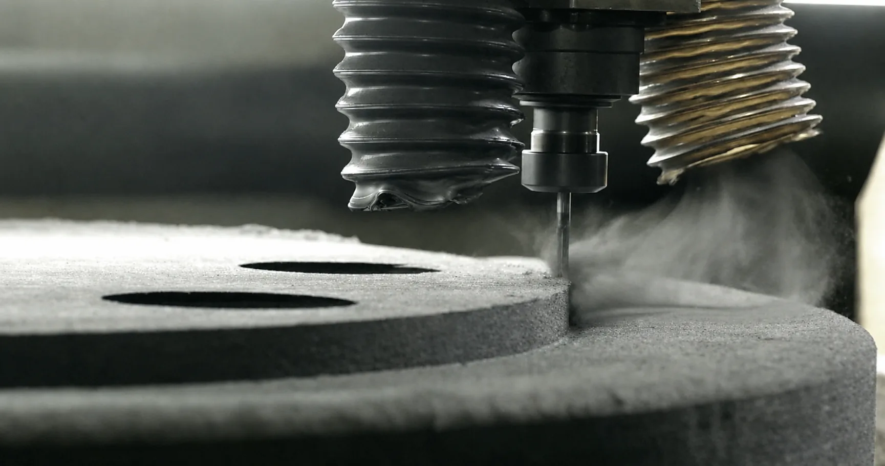
Modern fiber drawing furnaces require insulation cylinders with outer diameter approaching 1.7 m. At this scale, any delamination or seam becomes a failure-initiation point. AYD wet-laid molding produces single-piece ø1700 × 1500H × 200T cylinders and 1700 × 1700 × 200T plates with no seams.
Argon flow can reach several m/s for hundreds of hours of continuous operation. Conventional felt may shed particles, contaminating the fiber surface as mechanical break points. CarboniteX® surface options (graphite coating, graphite paper, graphite cloth, C/C composite) are matched to flow velocity and temperature.
Industrial-Grade High-Temperature Furnace Insulation
Typical industrial furnaces frequently exceed 1 m inner diameter and 3 m length. AYD rigid felt, as the outermost insulation, maintains hot-zone uniformity and holds dimensional stability across long operating cycles, preventing thermal drift from degrading process consistency.
AYD recommends a single-piece rigid felt configuration. Wet-laid molding produces seamless cylinders up to 1.7 m outer diameter with the geometric stability and concentricity required for large-bore chambers. The dense surface resists erosion from process gases and holds dimensions across multiple campaigns. Single-piece installation helps reduce loose-fiber contamination risk and can be more robust than multi-layer stacked configurations.
For applications with stringent energy-efficiency targets, an outer soft-felt wrap may be added as a supplemental radiation shield to further reduce radial heat loss. This is an optional add-on, evaluated by the AYD engineering team based on energy targets and operating cycle.
-
01
Semiconductor-Grade Deep Purification
On top of standard graphitization (ash ≤ 100 ppm), an additional > 2000°C vacuum high-temperature purification step brings ash below 20 ppm, verified by GDMS, with focused control over B, P, Al, and Fe, the elements directly affecting SiC / Si crystal yield.
-
02
UID Full Traceability
Each component is laser-etched with a unique identifier (UID), linking precursor batch, carbonization curve, graphitization log, density variation (4-decimal precision), GDMS purification report, and pre-shipment photo archive. This creates a product passport from raw pitch to finished part, suitable for technical audit by the customer's engineering team.
-
03
Large-Format Forming Capability
Wet-laid molding supports single-piece ø1700 × 1500H × 200T cylinders and 1700 × 1700 × 200T plates, the size class required by modern commercial fiber drawing furnaces and 12-inch CZ hot zones. Seamless forming and ±0.005 g/cm³ density precision across batches help reduce common failure modes in large-format components.
-
04
Surface Treatment Engineering
8 surface options (no treatment / graphite coating / graphite paper / graphite cloth / graphite cloth + graphite paper / carbon-carbon composite / CVD / others), matched to gas-flow velocity, chemistry, and mechanical stress. A second-pass purification follows surface treatment to restore purity, ensuring geometric and chemical consistency between surface and substrate.
Downloads
From spec selection to large-format customization.
Share your furnace type, operating temperature, atmosphere, hot-zone geometry, purity requirement, and procurement scale. AYD can confirm the precursor route (IPS, IRS, or IRL), purity grade, forming method, and surface treatment. Semiconductor-grade projects receive 24-hour technical response and qualification samples through bulk-scale delivery.